


- Product Description
-
Overview
GCK low-voltage withdrawable switchgear complies with GB7251.1, JB/T9661, IEC439-1 and other standards, and is suitable for 380-660V AC three-rate compensation. A mixed system of withdrawable and fixed drawers can be designed according to different needs. This product is for indoor use.
Environmental Conditions for Use
Ambient air temperature should not exceed +40℃ and should not be lower than -5℃. The average temperature within 24 hours should not exceed +35℃, and the altitude should not exceed 2000m.
The relative humidity of the surrounding air should not exceed 50% at the highest temperature of +40℃, and a higher relative humidity is allowed at lower temperatures (e.g., 90% at +20℃).
The inclination of the equipment to the vertical plane during installation should not exceed 5℃.
The equipment should be installed in places without violent vibration and impact, and in places where the electrical components will not be corroded.
For special requirements from the user, please consult the manufacturer.
Auxiliary Circuit Scheme
The GCK auxiliary circuit scheme is divided into AC and DC parts.
The auxiliary circuit scheme for the DC operating part is mainly used for low-voltage power supply systems in power plant substations and low-voltage power supply systems for generator sets, and the general control method for working (backup) power supply lines, power supply feeders, and motor feeders. The AC operating auxiliary scheme is mainly used for low-voltage systems in substations of factories, mines, and enterprises, as well as high-rise buildings. The auxiliary circuit scheme is designed based on the main circuit scheme, including power supply lines, feeders (PC), and motor feeders (MCC) operating control functional unit lines.
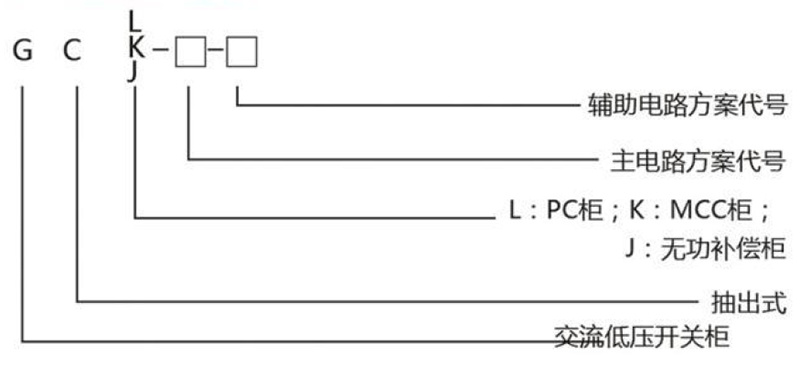
Product Model Meaning
Main Technical Parameters
Rated Voltage of Auxiliary Circuit V AC 380, 660 AC 220, 380 DC 110, 220 Rated Frequency Hz 50 (60) Rated Insulation Voltage V 660 (1000) Rated Current of Horizontal Busbar A ≤5000 Rated Current of Vertical Busbar A 630, 1000 Short-Time Withstand Current of Horizontal Busbar kA/1s 50, 80, 100 Peak Withstand Current of Horizontal Busbar kA/O.1s 105, 176, 220 Power Frequency Test (V/s) Main Circuit 2500 Auxiliary Circuit 1760 Busbar Three-Phase Four-Wire System A, B, C, PEN Three-Phase Three-Wire System A, B, C, N, PE Main Circuit Connector A 200, 400 Control Circuit Connector A 10, 20 IP30/NP40
Low-voltage power distribution equipment GCK
Share Now


- Product Description
-
Overview
GCK low-voltage withdrawable switchgear complies with GB7251.1, JB/T9661, IEC439-1 and other standards, and is suitable for 380-660V AC three-rate compensation. A mixed system of withdrawable and fixed drawers can be designed according to different needs. This product is for indoor use.
Environmental Conditions for Use
Ambient air temperature should not exceed +40℃ and should not be lower than -5℃. The average temperature within 24 hours should not exceed +35℃, and the altitude should not exceed 2000m.
The relative humidity of the surrounding air should not exceed 50% at the highest temperature of +40℃, and a higher relative humidity is allowed at lower temperatures (e.g., 90% at +20℃).
The inclination of the equipment to the vertical plane during installation should not exceed 5℃.
The equipment should be installed in places without violent vibration and impact, and in places where the electrical components will not be corroded.
For special requirements from the user, please consult the manufacturer.
Auxiliary Circuit Scheme
The GCK auxiliary circuit scheme is divided into AC and DC parts.
The auxiliary circuit scheme for the DC operating part is mainly used for low-voltage power supply systems in power plant substations and low-voltage power supply systems for generator sets, and the general control method for working (backup) power supply lines, power supply feeders, and motor feeders. The AC operating auxiliary scheme is mainly used for low-voltage systems in substations of factories, mines, and enterprises, as well as high-rise buildings. The auxiliary circuit scheme is designed based on the main circuit scheme, including power supply lines, feeders (PC), and motor feeders (MCC) operating control functional unit lines.
Product Model Meaning
Main Technical Parameters
Rated Voltage of Auxiliary Circuit V AC 380, 660 AC 220, 380 DC 110, 220 Rated Frequency Hz 50 (60) Rated Insulation Voltage V 660 (1000) Rated Current of Horizontal Busbar A ≤5000 Rated Current of Vertical Busbar A 630, 1000 Short-Time Withstand Current of Horizontal Busbar kA/1s 50, 80, 100 Peak Withstand Current of Horizontal Busbar kA/O.1s 105, 176, 220 Power Frequency Test (V/s) Main Circuit 2500 Auxiliary Circuit 1760 Busbar Three-Phase Four-Wire System A, B, C, PEN Three-Phase Three-Wire System A, B, C, N, PE Main Circuit Connector A 200, 400 Control Circuit Connector A 10, 20 IP30/NP40
Fill in your phone number and E-mail information, and we will contact you within one working day to solve your problems as soon as possible.


Quality is life, management creates efficiency
Contact Info
Mobile: +8613073125830
Tel: 0086-311-83880321
Email: 15614338905@163.com
Add: Hulu Town, Hualu District, Shijiazhuang City, Hebei Province
Scan the code to follow us

Official Account

Douyin
